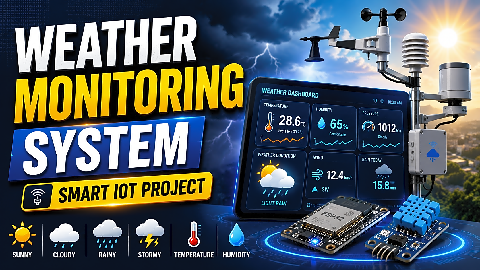
Weather Monitoring System Project Using IoT, ESP32 & Arduino
A Weather Monitoring System is a practical final-year project that measures real-time weather parameters such as temperature, humidity, pressure, rain, light intensity, and air quality using sensors. For the best final-year project version, use ESP32 + DHT22 + BMP280 + rain sensor + OLED display + ThingSpeak/Firebase dashboard.
This project is popular because it combines embedded systems, IoT, cloud data logging, dashboard visualization, and academic documentation in one working model.
For students, the goal is not only to build the circuit. You also need to explain the problem statement, system architecture, components, methodology, testing, output screens, source code logic, and viva answers. This guide covers everything needed to prepare a strong Weather Monitoring System final year project.
What Is a Weather Monitoring System?
A Weather Monitoring System is an electronic and IoT-based setup that collects local environmental data through sensors and displays it on an LCD, OLED, mobile app, or web dashboard.
Unlike a general weather forecast app, this project monitors weather conditions at a specific location such as a college lab, farm, greenhouse, rooftop, smart city model, or industrial site.
A typical system includes:
- Sensors for temperature, humidity, pressure, rain, air quality, and light
- A microcontroller such as Arduino, ESP32, or NodeMCU
- A display module for local readings
- WiFi connectivity for cloud data upload
- A dashboard for real-time graphs
- Alert logic for abnormal values
Weather data is widely used in real applications. OpenWeather, for example, provides APIs for current conditions, forecasts, historical archives, air quality, maps, and industry use cases.
How Does an IoT Based Weather Monitoring System Work?
The working process is simple:
- Sensors collect weather data from the environment.
- The microcontroller reads sensor values.
- The program converts raw readings into readable units.
- Values are displayed on OLED or LCD.
- ESP32 or NodeMCU sends the data to the cloud.
- The dashboard shows live graphs.
- Alerts are triggered when values cross limits.
For example, if the rain sensor detects water droplets, the system can display “Rain Detected” and send a notification through Blynk, Firebase, or a custom dashboard.
ThingSpeak is a strong dashboard option because it lets IoT devices aggregate, visualize, and analyze live cloud data streams. It also supports live visualization and alert-triggering workflows.
Best Components for Weather Monitoring System Project
|
Component |
Purpose |
Approx. Cost in India |
|
ESP32 |
WiFi-enabled IoT controller |
₹450–₹800 |
|
Arduino UNO |
Basic embedded controller |
₹400–₹700 |
|
NodeMCU ESP8266 |
Low-cost WiFi controller |
₹250–₹500 |
|
DHT11 |
Basic temperature/humidity sensor |
₹80–₹150 |
|
DHT22 |
Better temperature/humidity accuracy |
₹200–₹400 |
|
BMP180/BMP280 |
Atmospheric pressure sensor |
₹150–₹350 |
|
Rain sensor |
Rain detection |
₹80–₹180 |
|
MQ135 |
Air quality/gas monitoring |
₹150–₹300 |
|
LDR |
Light intensity detection |
₹20–₹80 |
|
OLED/LCD |
Local output display |
₹150–₹400 |
|
Breadboard/wires |
Circuit connections |
₹100–₹250 |
|
Power supply |
Stable system power |
₹150–₹500 |
Recommended stack: ESP32, DHT22, BMP280, rain sensor, MQ135, OLED display, and ThingSpeak/Firebase dashboard.
Arduino vs NodeMCU vs ESP32 for Weather Monitoring
|
Feature |
Arduino UNO |
NodeMCU ESP8266 |
ESP32 |
|
Best for |
Basic prototype |
Low-cost IoT |
Advanced IoT |
|
Built-in WiFi |
No |
Yes |
Yes |
|
Processing power |
Basic |
Moderate |
Better |
|
IoT dashboard |
Needs extra WiFi module |
Easy |
Easy |
|
Sensor support |
Good |
Good |
Excellent |
|
Final-year value |
Basic |
Good |
Best |
Best choice: Use ESP32 for a modern IoT weather station project. It has built-in WiFi, strong processing power, and better scalability. Espressif also maintains ESP-IDF as the official development framework for ESP32-family chips, which adds technical credibility for advanced documentation.
Weather Monitoring System Circuit Diagram and Pin Connections
Add a labeled circuit image in this section.
Suggested image filename: esp32-weather-monitoring-system-circuit-diagram.jpg
Suggested alt text: ESP32 weather monitoring system circuit diagram with DHT22, BMP280, rain sensor and OLED display
|
Sensor/Module |
ESP32 Pin |
Purpose |
|
DHT22 |
GPIO 4 |
Temperature and humidity |
|
BMP280 SDA |
GPIO 21 |
I2C data |
|
BMP280 SCL |
GPIO 22 |
I2C clock |
|
Rain Sensor AO |
GPIO 34 |
Rain detection |
|
MQ135 AO |
GPIO 35 |
Air quality reading |
|
OLED SDA |
GPIO 21 |
Display data |
|
OLED SCL |
GPIO 22 |
Display clock |
|
VCC |
3.3V/5V as required |
Power |
|
GND |
GND |
Common ground |
Always check sensor voltage requirements before connection. Some modules support 5V, while ESP32 GPIO pins use 3.3V logic.
Basic vs Advanced Weather Monitoring System
|
Version |
Features |
Best For |
|
Basic |
Temperature, humidity, LCD display |
Mini project |
|
Standard |
Temperature, humidity, pressure, rain sensor, OLED |
Diploma/BCA/BSc project |
|
Advanced |
ESP32, multiple sensors, cloud dashboard, alerts, data logging |
B.Tech/MCA final year project |
For FileMakr-style final-year submission, the advanced version is stronger because it supports documentation, screenshots, testing, source code explanation, and viva preparation.
Step-by-Step Implementation Guide
Step 1: Define the Project Scope
Decide which parameters your system will monitor. A strong project should include at least temperature, humidity, pressure, rain detection, and dashboard visualization.
Step 2: Select the Controller
Choose ESP32 if you want WiFi, cloud integration, and better project value. Choose Arduino only for a beginner-level embedded model.
Step 3: Connect the Sensors
Connect DHT22, BMP280, rain sensor, MQ135, and OLED display to the ESP32. Keep a common ground and avoid loose jumper connections during demo.
Step 4: Write the Source Code Logic
The source code should follow this structure:
- Import required sensor and WiFi libraries.
- Define sensor pins and dashboard credentials.
- Initialize DHT, BMP280, OLED, and WiFi.
- Read temperature, humidity, pressure, rain, and air quality values.
- Validate sensor readings.
- Display values on OLED.
- Send values to Firebase, ThingSpeak, or Blynk.
- Trigger alerts when thresholds are crossed.
This structure helps you explain the weather monitoring system project with source code during viva without showing unnecessary complexity.
Step 5: Build the Dashboard
Use ThingSpeak, Firebase, Blynk, or a custom web dashboard. Add separate charts for temperature, humidity, pressure, rain status, and air quality.
Step 6: Test the Project
Test each sensor separately before combining the full circuit.
|
Test Case |
Input Condition |
Expected Output |
|
Temperature sensor test |
Room temperature |
Value shown on OLED/dashboard |
|
Humidity test |
Normal room air |
Humidity percentage displayed |
|
Rain sensor test |
Water drop on plate |
Rain alert triggered |
|
WiFi test |
ESP32 connected |
Data uploaded to dashboard |
|
Threshold alert |
High temperature value |
Alert notification shown |
Weather Monitoring System Project Report Format
Your project report should include:
- Abstract
- Introduction
- Problem statement
- Objectives
- Literature review
- Hardware requirements
- Software requirements
- System architecture
- Circuit diagram
- Flowchart
- Algorithm
- Source code explanation
- Testing and validation
- Result screenshots
- Advantages
- Limitations
- Future scope
- Conclusion
- References
Sample Abstract
This project presents an IoT based Weather Monitoring System that measures real-time temperature, humidity, atmospheric pressure, rainfall, and air quality using environmental sensors. The collected data is processed by an ESP32 microcontroller and displayed on an OLED screen and cloud dashboard. The system helps users monitor local weather conditions remotely and can be extended for agriculture, smart city, greenhouse, and disaster alert applications.
Applications of Weather Monitoring System
A Weather Monitoring System can be used in:
- Smart agriculture
- Greenhouse monitoring
- College laboratories
- Smart city projects
- Rainfall and flood alerts
- Air quality observation
- Solar plant monitoring
- Industrial safety
- Environmental research
Common Mistakes Students Should Avoid
- Using only DHT11 and calling it a final-year project
- Not adding a cloud dashboard
- Ignoring sensor calibration
- Using loose breadboard wiring during demo
- Not explaining why ESP32 is better than Arduino
- Skipping testing screenshots
- Having no viva preparation
- Writing a weak project report without architecture and flowchart
Expert Tips to Improve Marks
- Use ESP32 instead of Arduino UNO for better IoT value.
- Add a dashboard with graphs, not just text output.
- Include rain alert or high-temperature alert logic.
- Compare local sensor data with an online weather API.
- Add a clean enclosure for better presentation.
- Include screenshots of OLED output and dashboard graphs.
- Add future scope such as AI prediction, solar power, GSM/SMS alerts, and agriculture automation.
Weather Monitoring System Viva Questions
|
Question |
What to Prepare |
|
What is a Weather Monitoring System? |
Definition and working |
|
Why did you use ESP32? |
WiFi, speed, IoT support |
|
Which sensors are used? |
DHT22, BMP280, rain sensor, MQ135 |
|
What is the role of DHT22? |
Temperature and humidity |
|
How is data sent to the cloud? |
WiFi + API/dashboard |
|
What happens if WiFi disconnects? |
Error handling/data retry |
|
Why is BMP280 used? |
Pressure measurement |
|
What is the future scope? |
AI, solar, SMS, agriculture |
|
What are the limitations? |
Sensor accuracy, power, calibration |
|
Can this project predict weather? |
Basic version monitors; advanced version can predict using historical data |
FAQs
What is a Weather Monitoring System project?
It is an IoT or embedded system project that collects real-time weather data using sensors and displays it locally or remotely.
Which sensor is used in Weather Monitoring System?
Common sensors include DHT11, DHT22, BMP180, BMP280, rain sensor, MQ135 air quality sensor, and LDR.
Which controller is best for Weather Monitoring System?
ESP32 is usually the best choice because it has built-in WiFi, good processing power, and strong IoT compatibility.
Can I make a Weather Monitoring System using Arduino?
Yes. Arduino can be used for a basic model, but you need an external WiFi module for IoT dashboard features.
Is Weather Monitoring System good for final year project?
Yes. It is a strong final-year project because it combines sensors, IoT, cloud dashboards, data logging, testing, and academic documentation.
What is the cost of Weather Monitoring System project?
A basic model may cost around ₹700–₹1,500, while an advanced ESP32 model with multiple sensors and display can cost ₹1,500–₹3,500 depending on components.
What is the future scope of Weather Monitoring System?
Future scope includes AI-based weather prediction, solar-powered deployment, SMS alerts, agriculture automation, flood warning, and mobile app integration.
Conclusion
A Weather Monitoring System is a practical and high-value project for students who want to demonstrate IoT, sensors, cloud computing, and real-time monitoring.
For the best final-year project, use ESP32, multiple sensors, a cloud dashboard, proper testing, and complete documentation. Your marks will improve when you can explain the circuit, source code logic, dashboard output, limitations, and future scope clearly.
Need a ready Weather Monitoring System project report, source code, PPT, synopsis, diagrams, and live demo support? Explore FileMakr’s final-year project resources and choose a project package that matches your degree and submission format.